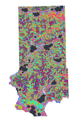
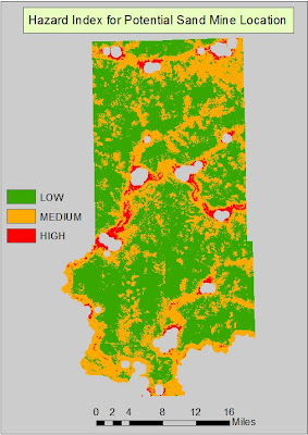
Friday, May 10, 2013

GIS II: Geoprocessing with Python Script

Introduction

This exercise dealt with using Python scripting to run an iterative script to run buffers around frac sand mine locations in Wisconsin. Python gives the analyst a dynamic and versatile way to run geoprocesssing tools. This language is the preferred scripting language used in ArcGIS. There are a variety of options in ArcGIS for running geoprocessing tools. First of all, there is the standard Toolbox in which there is a template where you enter the variables, output location, and any additional parameters. The downside of using the standalone toolbox is that you have to run the tool for each dataset separately which can take a lot of time and create a large amount of files. Another option is to use Model Builder in which multiple tools can be implemented at the same time in order to streamline data processing. Using Python scripting, the analyst can directly write out the process and define the variables directly withing the scripting window. Python also gives the analyst the advantage of creating tools or making adjustments to other tools. Either way, it can serve as a very powerful tool for geoprocessing tasks.

The objective for this exercise was to write an iterative feedback loop using Python to buffer mine locations 5 times; each time adding 1000 meters onto the previous buffer. This required using a "loop" structure which is basically a way of telling the computer the number of iterations to run as well as the increment value for each iteration. The looping function runs over a range of numbers which has three arguments: start, stop, and step. The start argument defines the beginning integer and up to, but not including (stop) the highest range value using an increment of size (step).

Methodology

So for this exercise, we want 5 buffers of 1000 meters which translates into: start = 1, stop = 5, and step = 1000m. Below is how this workflow is translated into Python scripting where each variable needs to be defined before writing the model.
Fig. 1 - Python script for running a buffer iteration on mine locations.
Once the workspace was defined (where the "mines.shp" is located), the variables were defined and then inserted into the appropriate spots within the Buffer_analysis template. Basically, this is what the Buffer tool looks like in Python script. Here, i = 1 is the starting integer and "while i <= 5" is telling the computer to stop at 5. Within the Buffer tool, "mines_buff" + str(bufdist) + ".shp" means that the script will add 1000 onto each name of the respective iteration shapefile. At the end of the Buffer_analysis parameters, "bufdist += 1000 means that for each iteration, add 1000m for the next buffer and "i += 1" is referred to as the counter which increases the value of i by 1.

Results/Discussion


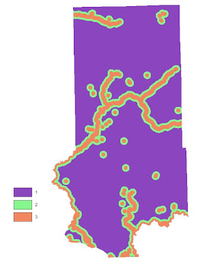
Fig. 2 - Results from buffer iteration script.

Fig. 3 - Zoomed in view of some sand mines in Trempeleau County, WI.

Using Python scripting to run the buffer processing saved a lot of time as using the Buffer tool via toolbox would have meant running each iteration separately. This exercise shows how powerful Python scripting can be and that it really has no limitations. While using Model Builder was useful in creating risk and suitability models, Python scripting would have streamlined alot of the processes as it could have been used to loop all of the buffers instead of using Euclidean Distance on every feature. After running Euclidean Distance, you still have to parse the distances into classes whereas with running a loop, you can define the distance break right away. The only downside is that Python takes awhile to learn whereas Model Builder is very straightforward. Investing the time into learning Python scripting would be very beneficial though as it is not as limited as Model Builder is.


Sunday, April 28, 2013

GIS II: Suitability Analysis with Rasters Part II


Introduction

This post is the second part of an exercise involving finding suitable land for a new sand mine and also for developing a hazard index for a new sand mine location. The Suitability Index was created in the previous post and now the focus is on the impact of sand mining by creating a Hazard Index based on a set of community and environmental factors: Proximity to Streams, Prime Farmland, Proximity to Residential Areas, Proximity to Schools, Visibility from Trails and Parks, and Wetlands. For each criteria, an impact figure will be assessed (3=High, 2=Medium, 1=Low) to determine the impact a sand mine would have if located in a certain area. High impact locations will be locations where mines should not be located. The rankings will then be summed up in order to create a Hazard Index. The study area is Trempeleau County, WI shown below.
Fig. 1 - Trempeleau County, the study area, shown in red.

Methodology

Once ArcMap was opened, the environments were set so that the workspace was assigned to my personal geodatabase, the coordinate system set to UTM 15N, output cell size at 30m, and the raster analysis mask set to the Trempeleau County feature class. Once the preliminary settings were defined, the next step was to tackle each objective one by one. All distances are in meters (m).
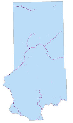
The first objective was to measure the impact on streams. The geodatabase for Trempeleau County was utilized to find the stream feature class called DNR-Hyro-junction. This feature contains many different types of streams such as combinations of Primary and Secondary streams, Perennial and Annual, and Overland and Instream flow. Using all of the combinations of streams meant that pretty much the whole county was streams. Running a Euclidean Distance on this would have not made much sense as the whole county would be considered a hazard area. Plus, not all of these streams are not around all of the time. To select the appropriate streams, a query was run to extract streams that were Perennial, Primary or Secondary, and Instream flow which would be the main streams in the county.
Fig. 2 - Queried streams used for Objective 1. 
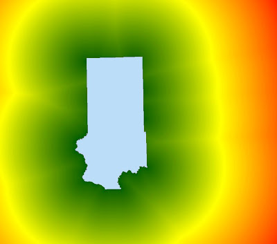
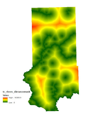
After the correct streams were selected, a Euclidean Distance was run based off of the streams feature class. Any time Euclidean Distance is used in this project, the processing extent needs to be greater than the size of Trempeleau County or else the extent will not extend to cover the whole county. From this, the Extract by Mask tool can be used to clip the Euclidean Distance to the extent of the county.

Fig. 3 - The first Euclidean Distance to ensure complete coverage of Trempeleau County.
Fig. 4 - Euclidean Distance from streams after Extract by Mask tool was used. 
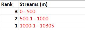
The next step was to reclassify the distances into 3 classes (High, Medium, Low). Since streams are such a precious resource, it was decided to give them a lot of breathing room. The following are the class breaks: (0-500) a 3, (500.1-1000) a 2, and (1000.1-10305) a 1.
Fig. 5 - Stream distance class breaks.

Fig. 6 - The model used to run Euclidean Distance and then reclassify the distances from streams.
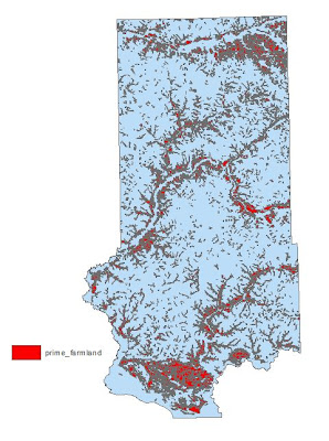
Objective 2 wants us to assess the risk to prime farmland. Once again, the Trempeleau County geodatabase was used to extract this information. There are varying types of farmland denoted by their production rates.Areas of prime farmland were identified through the attribute table and then extracted.

Fig. 7 - Prime farmland in Trempeleau County.
 Prime farmland can be disrupted by disturbing the soils. Once again, Euclidean Distance was used to determine the proper buffers. The classes were defined as: (0-100) a 3, (100.1-300) a 2, and (300-3515) a 1. It was felt that a 100m buffer was ample to protect areas of prime farmland. The Natural Breaks method was not used in this but rather rational thinking was applied to preserve these areas while at the same time not limiting potential locations. 
Fig. 8 - Class breaks for distance from prime farmland.
 
Fig. 9 - Model used to determine hazard to prime farmland.
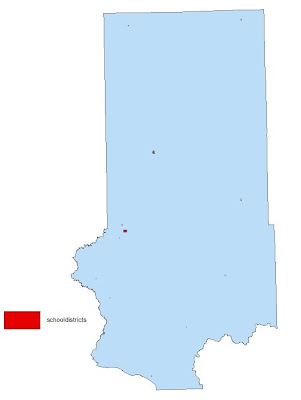
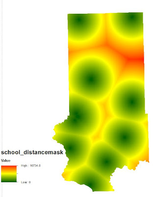
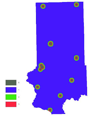
For Objective 3, the goal was to figure out the impact on schools. There is no schools feature class in the geodatabase so a different method needed to be used to determine school locations. A feature class called Parcels was located in the Trempeleau County geodatabase and was used to query out parcels which were owned by schools. School Districts could not be used as they contain the entire area closest to a particular school. Euclidean Distance was then run to be able to reclassify and rank distances.
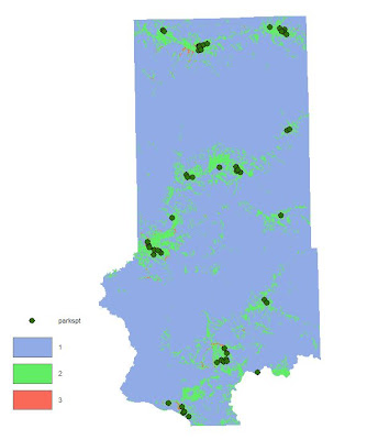
Fig. 10 - Areas in red denote parcels owned by schools.


Fig. 11 - Distance from schools determined by the Euclidean Distance tool.
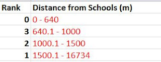
Since a mine must be located 640m away from a residential area for noise and dust concerns, the same distance will be applied to schools. Therefore the 3 classes were defined as: (0-640) = 0, (640.1-1000) = 3, (1000.1-1500) = 2, and (1500.1-16734 = 1. Once again subjective, yet logical thinking went into this.
Fig. 12 - Table ranking distance from schools.

Fig. 13 - Model used to develop a hazard index for schools. 
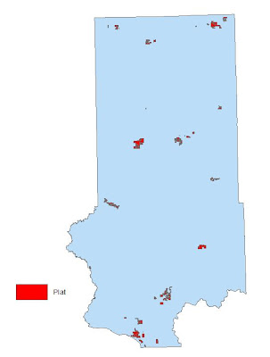
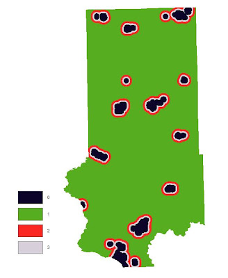
The goal for Objective 4 was to calculate distance from residential or populated areas. These areas are susceptible to noise and dust caused by mining operations. The distance a mine must be away from a residential area is at least 640 meters. There are several classes which contain information regarding residential areas. The LULC dataset includes such areas but also includes road networks with areas of residential so this is no good. The zoning feature class was not used either because the zoning polygons were too large and contained areas where there was no residence. Census data was also available but that too would have included too much area or too little depending on population density used to determine these areas. There was a feature called Plat in the geodatabase which was overlaid on top of the LULC raster. This feature did a very good job of outlining areas of residential without too much overestimating or underestimating. It was decided that this feature contained the least amount of erroneous areas and was used to represent residential areas.

Fig. - 14 - Plat parcels used to delineate areas of residential.


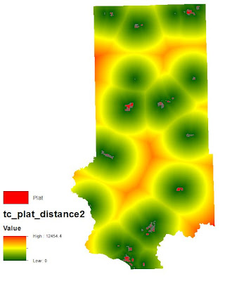
Fig. 15 - Noise/Dust shed determined by Euclidean Distance.
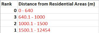
The distances were reclassified into 4 classes: (0-640) = 0, (640.1-1000) = 3, (1000.1-1500) = 2, and (1500.1 - 12454) = 1. It was determined that only a short extension beyond the 640m should be deemed a high hazard since 640m is already a large buffer.
Fig. 16 - Class breaks for distance from residential areas.

Fig. 17 - Model used to determine a noise/dust shed around residential areas. 
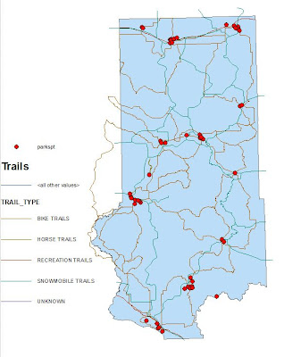
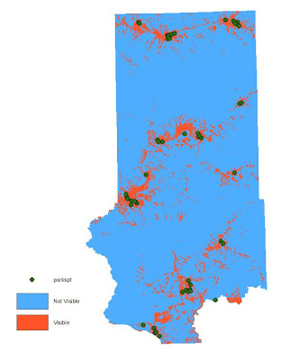
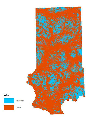
Objective 5 seeks to mitigate visibility of a sand mine from prime recreational areas such as trails and parks. In order to achieve this, a viewshed must be calculated from these feature classes. A viewshed uses elevation values from the DEM to determine areas that are visible and not visible from the feature classes. Running the Viewshed tool took an extremely long time on the Trails feature class. Since this tool only works on line or point features, the Parks feature class (polygon) needed to be converted into a point feature. The tool used for this conversion is called the Feature to Point tool located in Data Management. This tool assigned a point to the center of each park polygon.


Fig. 18 - Trails and Parks in Trempeleau County, WI.

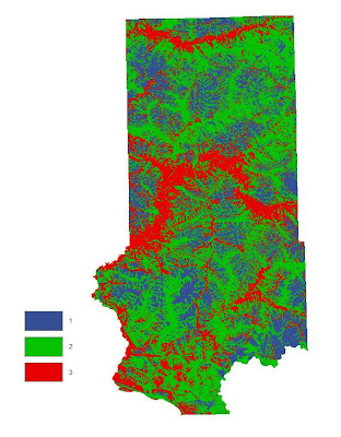
Fig. 19 - Areas of visibility and invisibility from park locations.
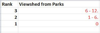
The park viewshed was then reclassified as follows: (0) = 1, (1-6) = 2, and (6-12) = 3. The values above zero indicate the number of times that spot can be seen from any other point on the map. Therefore, the higher values are areas of high visibility and are thus assigned a high hazard value. 
Fig. 20 - Viewshed from Parks class breaks.
 

Fig. 21 - Model used to determine viewshed from parks.

Fig. 22 - Areas of visibility and invisibility from trails in Trempeleau County.
The viewshed for trails was reclassified as follows: (0) = 1, (1-35) = 2, and (35-1822) = 3.
Fig. 23 - Trail viewshed class breaks.

Fig. 24 - Model used to determine viewshed from trails.
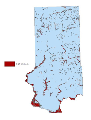
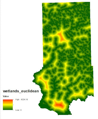
For the final objective, we were given the freedom to choose one more variable to include in the analysis. I chose to assess the hazard to wetlands. Even though wetlands were addressed in the Suitability Index, the feature class in the Trempeleau County geodatabase is far more detailed than the wetlands delineated in the LULC map. Wetlands are very fragile and are a very important component to the ecosystem. For these reasons, I chose to assess the hazards to wetlands as they are a very valuable resource and must be protected. Euclidean Distance was run and then reclassified.

Fig. 25 - Areas of wetlands in Trempeleau County.
Fig. 26 - Distance from wetlands.
The classification scheme for ranking hazards to wetlands is as follows: (0-300) = 3, (300.1-700) = 2, and (700.1 - 4324) = 1. It was decided that there should be a large buffer zone around wetlands to that any harmful constituents from a sand mine would be prevented from leaching into the wetlands.
Fig. 27 - Wetlands table class break rank.


Fig. 28 - Model used to determine hazards to wetlands.
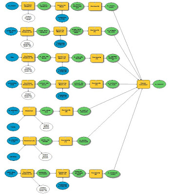
After all of the criteria had been properly ranked, they were added together using the Raster Calculator tool. This tool sums up all of the values at each cell location and then outputs the sums in a new raster. The range of sums in this exercise can be from 7 to 21.

Fig. 29 - Raster Calculator was used to add up all of the criteria rasters into a Hazard Index.

Results/Discussion

Below are the classified results from each objective and then the final Hazard Index. 


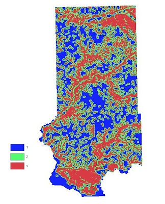
Fig. 30 - Hazard Index for streams.

Fig. 31 - Hazard Index for prime farmland.


Fig. 32 - Hazard Index for schools.


Fig. 33 - Hazard Index for residential areas.


Fig. 34 - Hazard Index for parks.

Fig. 35 - Hazard Index for trails.


Fig. 36 - Hazard Index for wetlands.  

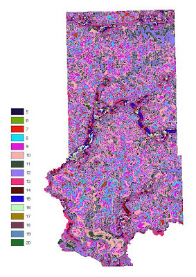
Fig. 37 - Summed up values of all criteria.
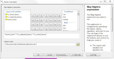
Areas of residential and schools are off limits for building a mine so they need to be excluded from the final Hazard Index.

Fig. 38 - Raster Calculator tool used to exclude schools and residential areas.

Fig. 39 - Schools and residential areas excluded from  Hazard Index.
The map in Fig. 32 needs to be simplified and so it was reclassified as follows: (7-10) = 1, (11-14) = 2, and (15-20) = 3. I chose these values because the lowest possible value is 5 which is low hazard where if all 7 inputs contained a value of 1 it would equal 7. The highest value for Medium is 14 where if the value of a cell is 2 (Medium rank) in the same cell for each raster, then the value would equal 14. Any value above 14 is considered a High Hazard area.
Fig. 40 - Model used to reclassify summed up values into a 3 rank Hazard Index.


Fig. 41 - Final Hazard Index map.
 
Here again, the class breaks chosen were subjective yet a logical though process was used to determine them. However, someone else could argue the breaks differently and thus create a different output. I thought there would be more high hazard areas in the final output. I was surprised that there was no location where the same cell for all inputs equaled 3 which would have given a summed value of 21. It appears that there are plenty of options for a new sand mine where the hazard would be minimal. This could look differently had the buffers around certain criteria been larger. I did not find it practical to extend a high hazard buffer a great distance from some of the features.

Conclusion

This exercise was a lot of fun to work through as we were given a lot of freedom in determining class breaks for the hazard rankings. This allowed us to really think about distances and try to visualize that which is kind of tough actually. However, this is a real world situation and it was very good experience processing a wide variety of data and deciding which data should be used to get the most accurate results.


GIS II: Suitability Analysis with Rasters

Introduction

Now that we have established where the mines are and also the closest railroad terminal to each mine location, it is time to find suitable land for future sand mines. There can be be countless paramater combinations used to determine where the most suitable locations are to accomodate a sand mine. Deciding on these factors can be a very subjective process. However, for the purpose of this project, we want to focus on some of the biggest factors, mostly environmental, that will determine which areas are best suited for a sand mine based on a ranking scale. We all know that a sand mine has major implications on the environment as well as it does to urban living as no one wants to live next to a noisy sand mining operation. The criteria that we will look at for a suitability model are: elevationk, land use/land cover, distance to rail terminals, slope, and depth to water table. Since we are limited by time constraints, the focus of this portion of the project will focus solely on Trempeleau County, WI.
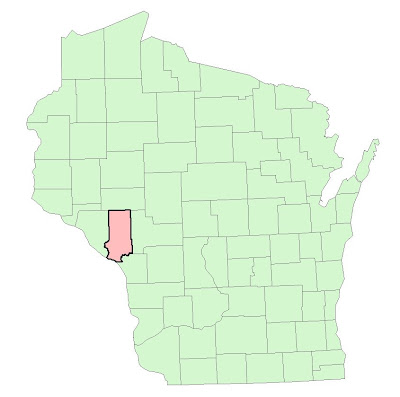
Fig. 1 - Trempeleau County, the study area, shown in red.

All of the datasets have been downloaded from a variety of sources and are in raster format. The criteria was broken into class breaks and then ranked for suitability (High = 3, Medium = 2, Low = 1). The final step will be to combine the five raster datasets into a suitability index model. All of the processes will be run through Model Builder.

Methodology

The first thing that we did was to set the geoprocessing environments so that all of the processes could be streamlined more efficiently. The workspace was set to the appropriate geodatabase, output coordinate system to UTM 15N, output cell size at 30m and the raster analysis mask set to the Trempeleau County boundary so all the rasters would be clipped to the same dimensions. After this was completed, the data was located and downloaded and then exported to the geodatabase. Objective 1 was to find suitable land based on elevation criteria. For this, a georeferenced bedrock geology map of westcentral Wisconsin was used to find where the most desirable geologic formations were located. These formations are identified as Jordan (gold) and Wonewoc (red) in the image below.
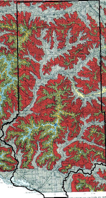
Fig. 2 - Geologic formations which can help indicate best areas for mining silica sand.
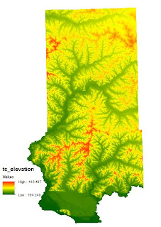
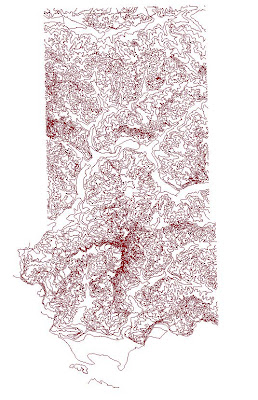
Since this data could not be found in digital format, we had to use a scanned map. For this reason, we cannot determine their locations using just the map. The way around this is to determine if there is a relationship between elevation and the geologic formations using a DEM. Contour lines with 10m intervals were then propogated from the DEM to give us a digital feature to work with for identifying exact locations. Once this was done and we figured out the elevation ranges, we turned back to the DEM to reclassify it based on elevation rankings. It was apparent that the Jordon deposits were located at a higher elevation then the Wonewoc deposits therefore necessitating the higher elevations (340-416) to receive a rank of 3, intermediate elevations (260-340) a 2, and lowest elevations (194-260) a 1.
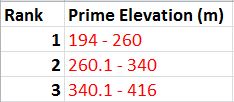
Fig. 3 - Elevation class break table.

The Wonewock deposits were found in a combination of the three but mostly in the intermediate elevations. The classification method used was the Jenks Natural Breaks method since the elevations were pretty well distributed. The Reclassify tool was added to Model Builder and the parameters set to those mentioned above.
Fig. 4 - Model used to reclassify the elevation ranges.
Fig. 5 - Elevation range of Trempeleau County.
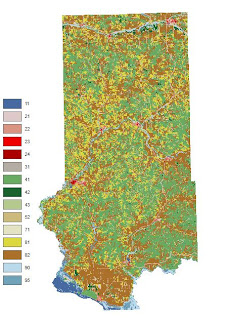
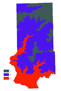
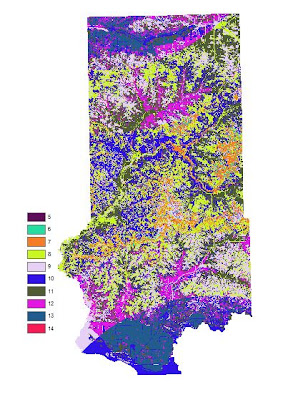
The task for Objective 2 was to find suitable land based on land use criteria. A land use/land cover (LULC) map for Trempeleau County was downloaded from the National Land Cover Dataset (NLCD). The image was classified into: Water, Urban/Built-Up, Barren, Agriculture, Herbaceous/Shrub, Forest, and Wetlands. The determining factor in ranking the LULC was the effort required to clear the land for a sand mine. Since Water, Urban/Built-Up, and Wetlands are obviously inappropriate locations for a mine location, they received a rank of 0. Forest was considered the most difficult to prepare and clear for a sand mining so it received a rank of 1. Herbaceous/Shrubland is listed as grasslands or shrubs with a canopy less than 5m tall. This type of land would be relatively easy to clear so it received a rank of 2. Finally, Barren and Agriculture are already cleared lands to these would be the best locations and they were given a rank of 3.
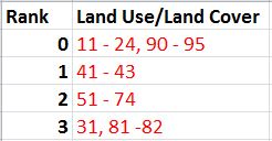
Fig. 6 - LULC class break table via codes from LULC Classification Legend below.
An argument could be made that agricultural land should be preserved based on it's productivity purposes but it was felt that since we are looking at the effort needed to clear the land it would be given the highest rank.
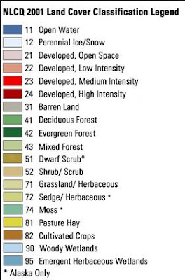
Fig. 6 - NLCD 2001 LULC legend used to determine  areas of suitability.

Fig. 6 - Model used to reclassify the LULC raster into a suitability rank.
Fig. 7 - Land Use/Land Cover (LULC) of Trempeleau County.
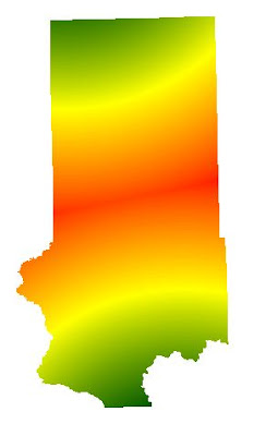
Objective 3 wanted us to find suitable land for the proximity to railroads. Finding distance to railroads is not practical since you can't load the rail cars at any given point on the rail. Therefore, instead of using railroads, rail terminals was used instead because these are the loading stations. For this process, the Euclidean distance needed to be used. Euclidean distance gives an output of straightline distance from a vector feature class. There are no rail terminals located within Trempeleau County. There is a terminal to the north and a terminal to the south of which are the closest to any location within Trempeleau County. Since Euclidean Distance is only run to the extent of the furthest feature, a portion of Trempeleau County was left out.
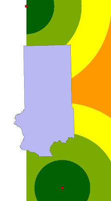
Fig. 8 - Euclidean Distance from rail terminals which left out a portion of Trempeleau County.
A query was run to extract the counties surrounding Trempeleau County so that the Euclidean distance would cover the whole county based on the target rail terminals.
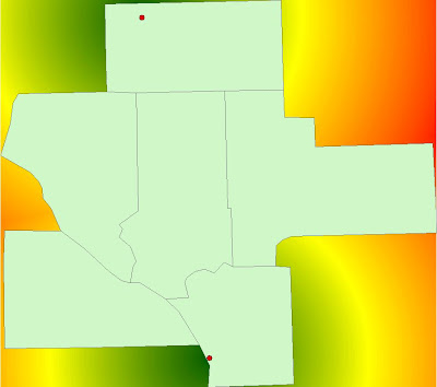
Fig. 9 - Euclidean Distance was run again to ensure full coverage of Trempeleau County.
Fig. 10 - The raster above was the masked to the extent of Trempeleau County.
The next step was to reclassify the Euclidean Distance based on the distance from rail terminals. Once again the Natural Breaks method was used to determine class breaks for the distances. The shortest distance range (13-21 miles) was ranked highest at 3. The intermediate distance (21.1-29 miles) was given a rank of 2 and the furthest distance (29.1-37 miles) was given a ranking of 1.
Fig. 11 - Class break table based on Euclidean Distance.

Fig. 12 - Model showing the workflow of masking and reclassifying the raster based on Euclidean Distance.

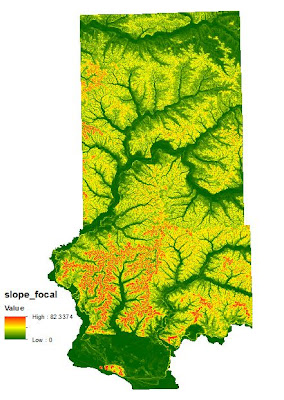
For Objective 4, we needed to find suitable land based on slope. The DEM stores elevation data and can be utilized give an output with calculated slope. The output value was set to "percent rise" to ensure this. The output was very detailed and contained a "salt and pepper" look. The slope values needed to be averaged out to give the raster a smoother look. The appropriate tool to do this is called Focal Statistics. This tool passes a 3x3 cell window over the raster to average out the values.
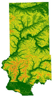
Fig. 13 - The original slope output containing the "salt and pepper" look.
Fig. 14 - Slope raster after being filtered to average out slope values giving it a smoother appearance.

After the Focal filter had been passed over the raster, the next step was to reclassify the raster based on slope values. It was determined that the more desirable locations would be located in areas with a lower slope gradient. Therefore the class breaks were as follows: low slope (0-10) was ranked at 3, medium slope (10.1-25) a rank of 2, and high slope (25.1-82) a rank of 1.
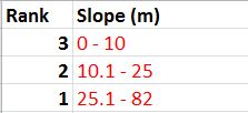
Fig. 15 - Slope criteria table rank.

Fig. 16 - Workflow to average slope values and then to reclassify it for suitability.

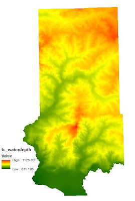
The 5th and final objective was to assess suitability based on water table depth. Mining companies prefer to build their mines on a location where the water table is close to the surface. A water table elevation map was downloaded from the Wisconsin Geological Survey in the form of a coverage (e00). This type of file is not directly supported in ArcMap. It was necessary to import this coverage running a tool called "Import from e00 (Conversion)". This tool will convert the coverage into an arc feature class so that it will then be compatible with the ArcMap software. Since this is a contour feature class, it is a vector, so it was necessary to convert the contours into a raster so that it could be used for analysis with the other rasters. The tool used for this conversion is called "Topo to Raster" which interpolates a hydrologically correct raster surface from point, line, and polygon data. The value field was set to the Water Table Depth field and type set to Contours.
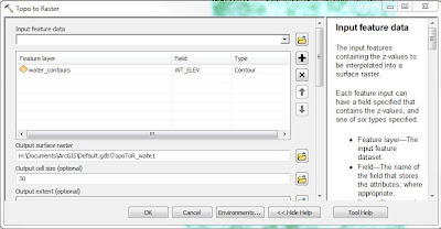
Fig. 17 - The Topo to Raster tool was used to convert a contour feature into a raster.
Fig. 18 - Imported contour line file for water depth table.
Fig. 19 - Top to Raster conversion.

Fig. 20 - Water table depth reclassification model.
The classification method used on the water depth table was to break the range of values into three classes using Natural Breaks. The classes were then ranked as follows: (611-780) was given a 3, (780.1-930) a 2, and (930.1-1125) a 1.
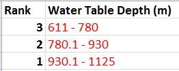
Fig. 21 - Table ranking water table depth criteria.

Results/Discussion

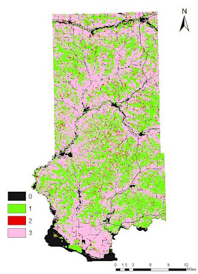
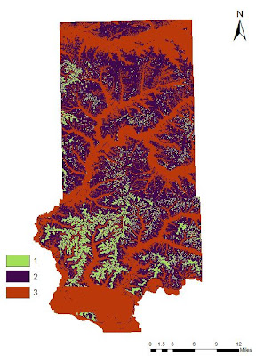
Below are the ranked rasters for each objective stated above. Remember that a 3 means best location and a 1 means poor location. A value of 0 means that these areas are off limits.
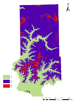
Fig. 22 - Elevation ranked according to geologic deposit locations.


Fig. 23 - Reclassified LULC raster showing the ranked areas of suitability.
The areas containing a 0 value are regions defined as water, wetlands, and urban. These areas are off limits.
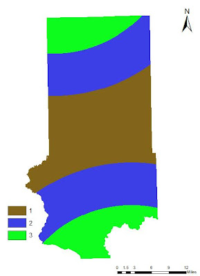
Fig. 24 - Reclassified raster showing ranked Euclidean Distance from rail terminals.

Fig. 25 - Ranked suitability raster for slope.


Fig. 26 - Water table depth rank.
The 5 ranked suitability rasters were then added together via the Raster Calculator tool. This tool adds together the ranked values of each pixel on each raster and then creates a new raster containing the summed up values. The lowest possible value is a 5 and the highest value can be a 15 (3x5).
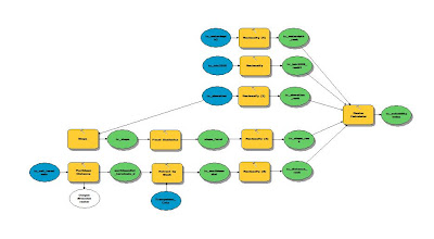

Fig. 27 - Raster Calculator used to sum up all of the criteria rasters.

Fig. 28 - Ranked Suitability Index based on 5 criteria.
It turns out that there is no location in which the maximum suitability exists on all 5 rasters so the highest ranking is a 14 vs. a 15. It was then necessary to make the LULC raster into binary so areas of residential, water, and wetlands are given a 0 value and all other acceptable areas a 1. This was then multiplied by the raster in Fig. 25 so that areas off limits for a sand mine are then coded as 0 and all other values retain their original values. The Index was then reclassified into 3 classes: (5-7) = 1, (8-10) = 2, and (11-14) = 3.
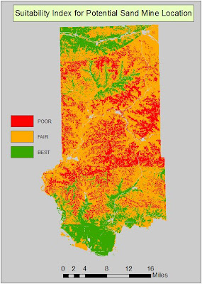


Fig. 29 - Final Suitability Index map.
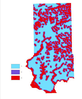

Since the class breaks were defined using the discretion of the modeler, the output can vary depending on how the user breaks the classes up for suitability. For this reason, the results can be very subjective. This is why the user needs to have a reason for how the classes are broken up as it can alter the output. That being said, I am very confident with my decisions in that regard and believe the output Suitability Index illustrates a logical data flow and can be implemented in a plan for finding optimal locations for a new sand mine.

Conclusion

This exercise was a very valuable learning experience as we got a chance to use skills learned in the classroom and apply them to a real world situation. This project was a lot of fun to work on especially being given the responsibilities of downloading the data, setting up environments, using logic, and building models to expedite the processes involved. A few speed bumps were encountered along the way but figuring out what is causing the problem and being able to fix it allows the user to develop great troubleshooting skills.